
")
")
1. GENERAL INFORMATIONS
GH 225-630 type machines are designed to meet and exceed the rigorous performance requirements of industrial applications.
Their exemplary electrical and mechanical designs ensure flawless operation in the most severe, heavy duty service.
All stator cores contain high performance electrical steel laminations, with compensating windings provided in the main poles.
The standard winding insulation system employs Class H materials, but standard performance is limited to Class F temperatures to extend machine life. Where required, size GH 225 can be supplied without compensation.
Mechanically, modular components are featured to allow the greatest flexibility to meet Customer’s varied needs. GH four-pole series of motors utilizes frames having seven shaft axis heights: 225, 250, 280, 315, 355, 400, and 450 mm.
GH six-pole series covers three shaft axis heights: 500, 560, and 630 mm. While the usual mounting arrangement is horizontal foot mounted (IM B3 [code I] or IM 1001 [code II] in accordance with EN 60034-7) alternate arrangements are available on request.
The factories are equipped with up-to-date machinery and modern manufacturing techniques for the production of the highest quality interchangeable parts.
The motors described in this catalogue cover a range of power output from 160 kW at 1500 rpm (1,019 kNm) [GH225SK] to 1800 kW at 500 rpm (34,38 kNm) [GH630ZK
2. STANDARDS AND QUALITY
2.1. REFERENCE STANDARDS
The GH series of motors is designed and manufactured to comply with the International Standard IEC 34-1 and the CENELEC harmonized standards EN 60034 and HD53 for European countries.
In particular, the ratings and performance characteristics are in full compliance with EN 60034-1.
Upon request, motors can be supplied to meet the performance requirements of other standards (e.g. NEMA MG-1).
2.2. CE MARKING
GH series machines are manufactured in conformance to European Directive 73/23/EEC mod. 93/68/EEC (LVD) and meet the essential protective requirements specified in the European Directive 89/336/ EEC (EMC) mod. 92/31/EEC and 93/68/EEC. The “CE” mark is applied to each machine to certify compliance with these directives.
2.3 QUALITY SYSTEM
The Quality System of ANSALDO SISTEMI INDUSTRIALI – IEG covers the design, manufacturing and testing of DC machines. Related activities, such as procurement, component quality verification, project management and customer service, are also included within the system’s comprehensive scope.
This Quality System is certified by CISQ/RlNa (certification n. 50/92) – EQNet (Registration n. IT-2624) to comply with European standards UNI-EN 29001 (ISO 9001).
3. DESIGN FEATURES
3.1. ROTOR
The armature core is made up of preinsulated steel laminations, and is heat shrunk on the shaft to obtain rigid mechanical integrity.
Armature windings are manufactured from preinsulated copper rectangular wire having a Class H enamel coating or enamel covered with glass yarn.
Ground insulation is NOMEX®.
Wave or frog-leg armature winding patterns are employed according to the customer’s requirements for electrical performance.
3.2. COMMUTATOR
The commutator is designed to have an overspeed capability greater than that required of the motor.
To insure long term operational stability, these components are mechanically rotated and thermally
aged prior to being secured to the shaft by an interference fit.
3.3 STATOR
The magnetically active stator core component, main and commutating poles are fully laminated to provide for rapid response times to transients in load or speed.
During assembly these laminations are hydraulically compressed under tons of pressure, then bound to
form a rigid, stable assembly.
Stator coils are formed from Class H insulated copper wire, and include NOMEX® ground wall insulation materials.
These coils are bonded to the pole cores with special epoxy resins and interconnected with flexible cables.
These cables are braced with high strength, extreme temperature tolerant lacing material.
After completion, stator assembly is Vacuum Pressure Impregnated (VPI) with Class H resin and cured in a temperature controlled oven.
For severe applications where high humidity, carbon dust or abrasive material is encountered, an additional high build resin coating is applied by immersion and thermal catalyzation.
3.4 BRUSHHOLDER YOKE
Designed for strength and stiffness, the brush yoke is mounted to the mechanically rigid end shield.
This yoke supports the brush holders, and allows individual adjustment of the brushes for optimal
neutral zone alignment.
Such design also incorporates sensitivity for the 1% positioning required for tough bi-directional
rotating applications.
The brushes are split type, and are manufactured from high quality electrographitic grade
material.
The brushes are selected to consider the motor rating, application and environmental conditions.
3.5 BEARINGS
Bearings are sized in accordance with the largest rated torque for that frame size, regardless of the length of the machine, to provide for lower bearing temperatures, improved vibrational stability and improved bearing life.
In horizontal, direct coupled use, the B10 life is in excess of 40,000 hours, and 20,000 hours for belted applications.
Bearing seals are provided for totally enclosed motors having an IP 55 degree of protection.
3.6 BELTED AND RADIAL THRUST APPLICATION
Power transmission components (pulleys, sheaves and belts) must be designed and selected in accordance with the manufacturers recommendations.
Once the motor side pulley or sheave has been selected, the allowable radial (side) thrust load must be within the values declared for ball bearings or roller bearings.
Larger pulley diameters may be considered, with the limit that the pulley length must always be smaller than two times the shaft extension length.
Additionally, an air gap of 10 mm be provided between the pulley and motor end shield (bearing bracket).
4. CONSTRUCTION FEATURES
4.1 COUPLING AND SHAFT EXTENSION
Standard machines are furnished with one drive end extension which is cylindrical with a keyway (IM 1001). On request, machines are available with two shaft extensions (IM 1002) for a tandem arrangement, and the shaft end dimensions may be of different size from the standard solution.
Unless otherwise specified, standard machines are designed for direct drive using flexible type couplings.
4.2 MOUNTING ARRANGEMENT
Machines are furnished in accordance with EN 60034-7 standard mounting arrangement IM B3 (code I) or IM 1001 (code II).
Vertical machines in the IM V1 (code I) or IM 3011(code II) mounting arrangement available upon request.
Available also the IM B5 or IM 3001 arrangement.
4.3 DEGREE OF PROTECTION
Machines are normally furnished with one of the following degrees of protection, in accordance with EN 60034-5: IP 23 S: Protected machine IP 44 : Enclosed machine
Other enclosures or more restrictive degrees of protection are available upon request.
4.4 COOLING METHOD
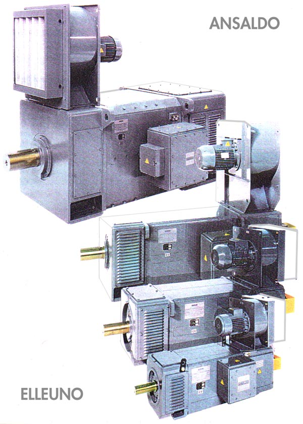
ANSALDO provides various standard cooling methods.
Cooling method IC 666 (air-to-air heat exchanger with primary and secondary air blowers) requires
special handling by the factory.
Applications using water-to-air heat exchangers may require special handling due to water temperatures or non-fresh water sources.
4.5 NOISE LEVEL
Motor noise levels are evaluated on the weighted A scale basis, by either the Sound Pressure Level (Lp) or the Sound Power Level (Lw), and are measured in accordance with ISO 1680/1.
Standard machine noise levels comply with the limits of EN 60034-9.
Machines with reduced noise levels can be furnished upon request.
4.6 VIBRATIONS AND BALANCING
Where the shaft extension includes a keyway, rotor balancing is performed with a half key secured in the slot.
Otherwise, the rotor is balanced without the half coupling, pulley or other device mounted.
Any component added to the rotor after this must be independently balanced.
All machines comply with IEC 34-14 and HD 53.14.51 (as harmonized by CENELEC)
with vibration level “R” for frames GH 132 through GH 400. Frame GH 450 is balanced according to level “N”.
On request, the motors may be supplied in compliance with level “R” (reduced) or “S” (special).
Motor vibration levels are rms values of velocity (Veff), and have a tolerance of +10%.
Where the operating speed is lower than 600 rpm, vibration level is defined in terms of the maximum amplitude (peak-to-peak), and measured in microns.
4.7 CONDUIT BOX
Standard machines are furnished with terminal board type connections enclosed in a large conduit
box having an IP 55 degree of protection.
Cable entrance cover plates are furnished blank to allow for field drilling.
This conduit box is usually mounted on the right hand side of the machine when viewed from the drive end. Where a blower assembly is furnished, the conduit box must be mounted on the opposite side.
On request, loose type connection cables or incoming cable glands can be provided.
4.8 GROUND TERMINALS
To ground the machine, two terminals are provided with threaded holes and screws.
One terminal is available in the conduit box; the other is on the frame near the box, complete of identification nameplate.
5. MOTOR SELECTION BY RATING AND OPERATING CONDITIONS
5.1 RATINGS
Maximum ratings, with de-rating curves for field weakening operation, for each GH motor design are given in the tables of the specific motor brochures, where reference drawings for these standard machines are also provided.
These are valid for:
- Continuous duty (S1), per EN 60034-1.
- Cooling by separate ventilation, or by water-to-air heat exchanger(IC 06, IC 17, IC 37, IC 86 W per EN 60034-5).
- Cooling air temperature not exceeding 40°C, or cooling water temperature not exceeding 30°C.
- Altitude of the installation not exceeding 1000 meters.
- Power supply from a static converter connected in a fully controlled three-phase bridge (identification
code for converter connection: B6C per IEC 971).
The maximum current ripple factor, calculated as shown in EN 60034-1 is 18%.
The manufacturer must be consulted for other power supply conditions to determine if an external series inductor must be added.
Current ripple adversely effects the commutating capability and motor losses.
It is necessary that the maximum value of current asymmetry from the converter is 10%, where the current asymmetry is defined as the difference between the maximum peak value of the current expressed as percent of the rated armature current.
- Speed regulation lower than 1:1.5 by means of field weakening control for non-compensated machines, and 1:2.5 for compensated machines.
The manufacturer must be consulted for higher speed range regulation by means of field weakening control.
- Maximum load of 160% for 15 s per EN 60034-1. The duty cycle should be such that the rms current does
not exceed the rated current.
Class H motor insulation system, limited to Class F temperature rises per EN 60034-1.
- The manufacturer must be consulted for other temperature rises (Class H or Class B).
5.2 MAXIMUM LOADS
Maximum loading is subject to a specific set of conditions.
GH type machines are designed to meet and exceed the severe operating demands of industrial applications.
Capabilities of uncompensated and compensated wound machines are noted below:
Non-compensated sizes GH 132-225
The maximum torque is 1.6 times the rated torque for 15 s on the basis of approximately 200% instantaneous current with such cycling that the rms load value during a 5 minute load cycle does
not exceed the rated armature current.
Motors with a stabilizing series field are capable of carrying out a torque 1.8-2 times the rated torque with a current twice the rated current.
Compensated sizes GH 132-450
The maximum torque is 1.8 times the rated torque for 15 s on the basis of approximately 200% current with such cycling that the rms load value during a 5 minute load cycle does not exceed the rated armature
current.
5.3 CURRENT RATE-OF-RISE
A current rate-of-rise of 200 In/s at rated current and speed is generally allowed.
5.4 SPEED REGULATION
Values of maximum allowable speeds are listed in the operator manual.
Each motor can operate at full field (with speed control) at constant torque up to one fiftieth (1/50) of the base speed without significant torque pulsation.
Each motor can operate with field weakening speed regulation (with a stabilizing series field or compensating winding) up to the maximum mechanical speed.
When the motor speed is controlled by field weakening, it is necessary to reduce the rating given in the tables in accordance with the derating diagram.
In particular:
P = Pn x K
where:
P = maximum allowable output power
Pn = output power given in the tables
K = derating coefficient shown in the diagrams versus maximum required speed and winding code
For each frame size, the derating diagram is furnished for the machine having the maximum frame length. For motors having a shorter frame length, the maximum speed is obtained by multiplying the speed determined from the diagram by the de-rating coefficients given in the tables.
5.5 DUTY WITH LARGE SPEED REGULATION
The use of mixed control systems provides a large increase in the allowable speed range, including overloads.
This type of speed regulation reaches maximum speed by a combination of increasing armature voltage (and corresponding decrease in current) and field weakening.
This arrangement provides the advantages of operating with a pre-determined ratio of field weakening and the benefit of reducing the armature current in the ratio of the speed at the beginning of the field weakening to that of the base speed.
It is advantageous to commutation since it depends not only on the current value (reactance voltage) but also on the saturation of the commutating pole circuit (divergent bands).
The adoption of a mixed type speed control (or “false characteristic”) does not involve changes in either the frame size or core length.
While the static converter size is increased for larger current, the cost is compensated by the improved
operation of the complete drive system.
5.6 EXCITATION
All standard motors, with or without compensating windings, are designed for separate excitation without the use of a stabilizing series winding.
Non-compensated motors can be fitted with a stabilizing series field upon request.
Standard excitation voltages are 220 V and 330 V, with alternate voltages available upon request.
5.7 ACCESSORIES
Space heaters
Space heaters of armoured type can be provided on request. Typical ratings are given in Table 14 for 220 V, single phase, 50 Hz power supply.
Thermostats for space heaters
When automatic control of the space heaters is desired, thermostatic space heater control is available upon request.
Air flow switch
On request, a pressure switch is mounted on motors with separate ventilation blowers or air duct connections to detect the presence, or absence, of cooling air.